What is it?
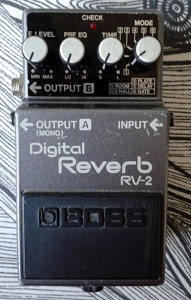
Boss RV-2 Digital Reverb. Made in japan, 1987.
Got the unit in a bag of crap i bought from one local guy. The unit was missing a bottom plate altogether and it was not in working condition. Checked the insides around for a while and there were just couple of loose wires coming from the jacks to the board. Soldered those back to their places and got it running. The missing bottom plate was another issue. Where was i to acquire a grey label Boss bottom plate? Nowhere. But i had an old japanese DD-3 with burned chip in a spare parts box, so i scavenged the plate from that one. It is with blue label and from around 1988, so it’s not the closest possible match, but it’ll have to suffice.
This is likely to be the very first digital reverb in a compact pedal form ever. With all the features of professional rack mount units included, it’s bound to be quite complex design.
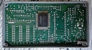
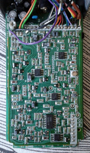
I may have written about filled boards before, but this one takes the grand price. The boards are made with tiniest SMD-components and the design still had no chance of fitting in a standard Boss enclosure. Didn’t notice it at first. But yes. The box is slightly taller than the standard boxes. Apparently, the taller box is used only in PSM-5 and RV-2. PSM-5 needs the taller box because of the jacks at where the knobs normally are. This one however.. Needs all the possible space to house the boards. All the other designs fit in the standard one.
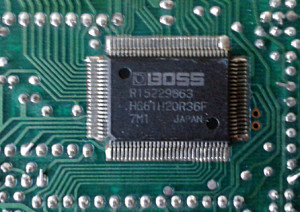
These pictures do not cover the detail of two stacked boards too well, but that’s how it’s made. With two massively crowded, two-sided boards bonded together. More as a detail, even the digital chips are Boss-branded. This must have been pretty expensive thing to manufacture…
Quick googling around didn’t give out a schematic, but i’d like to see one – just to see if i could understand anything of it.. All in all, this is the most complex design in such a small enclosure i’ve ever seen. The board design has more components on it than your 90’s PC motherboard. And it’s still nothing more than a reverb unit, mimicking a full fledged rack mount monster. The features easily trump most of the modern table top units. Six modes from plate to gate, to room, to hall and panned reverbs. All with adjustable time from 0.2 to 10 seconds. Then there’s the pre-EQ control for tuning the frequency range that we want to reverberate. And mix control, of course. Overall, very controllable.
It does surprise me that the current market value of these units is not higher. First of all, these were only made in japan for less than a year and a half, from 1987 to 1988. Second, the engineering is more than just respectable. Third…
How does it sound?
It doesn’t sound bad at all. Sure, it may not last too many rounds in the same cage with high-end brand rack mounted studio reverbs.. But then again. This is just a tiny pedal from Boss’ compact series and it’s meant to be used with a guitar. As a guitar effect? Just beautiful from small ambient plate to massive, wettter-than-ever surf reverberation. Good controls, good overall feel and sound. Where some (or be exact, most) Boss compact pedals leave me with no feelings at all, this one is not one of them. It’s versatile and usable pedal. And on top of that it is an important piece of stompbox history. So.. If you have a grey label bottom plate laying around without a pedal, drop me a line…


hi there,
here is the schematic:
http://www.synfo.nl/servicemanuals/Boss/RV-2_SERVICE_NOTES.pdf
I bought one but it needs to be reparied ´cos its e.level pot only shows the wet signal, the dry signal is disappeared. Besides the previous owner disconected the battery cables and I can´t find where they should be soldered. Would you mind telling me where I should solder them ?
thanks for your answer.
RV-2 works only with adapter. Not with batteries.
Hey, how are you, would you please send me a better picture of the top left corner where the IC1 is positioned? I got the pedal where somebody replaced the 5V stabilizer with a transistor and I can’t wrap my head around in which way the TO-92 should be facing. Schematic says pin 1 (INPUT) goes to the DC connector and pin 3 (OUTPUT) is connected to the Vcc in the digital section. But the board layout shows the TO-92 the other way around. Thank you!
Ddt