So what shortcomings are we talking about this time?
Shortcomings of a classic fuzz circuits. Sure i could rave on about hundreds and hundreds of boosters, overdrives and distortions that simply can’t overcome the unity level of your guitar. In my books that’s a shortcoming. But maybe i’ll reserve those for another part of my writings. Let’s just go with the fuzzes for now. To get to the bottom of this behavior, we must understand what the guitars were like 50 years ago. The term “vintage output” for pickups does have a meaning. DiMarzio was the first manufacturer to offer aftermarket pickups. Meaning that before 1972, swapping the pups for better ones wasn’t exactly an option (for the word better, we’d need to define what’s better, but you’ll get the idea). Swapping pickups on existing guitars and paying more attention to those became widely popular later in the eighties. Which means that all the classic effect pedals from 1966, all the way to beginning of 80’s were designed to work with old school standard pickups that were shipped with sold guitars. Usually having low or lowish output pickups. Think about PAF style humbuckers for example. They have very nice tone, but the output is still low. I’ve noted before that once your pickups have high enough output, that can turn the effect to sound mushy, and simply put, bad. Other chance is that the output is too high for the circuit design to add any real current to the signal.
To me, it’s very annoying to notice that otherwise good sounding re-issue of Fuzz Face can’t boost the signal coming from my favorite humbuckers. Now, these humbuckers give out highish output and they sound reasonably good without being too harsh. When i play with clean sound for most of a song and want the upcoming lead to stand out, i simply can’t choose this Fuzz Face re-issue to be the pedal to do that. Not by itself, at least. I’ve seen this same behavior with many other effect designs from the past too.
Got it. So how to overcome this issue?
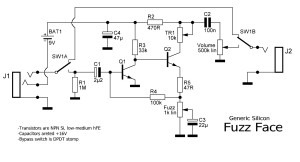
Breaking every single rule i ever had for my colorless writings, here’s a schematic for very generic silicon fuzz face. (Sure, these images have no color except for black and white, so i can let it slide)
You can find about a hundred similar schematics with internet image search. There is also very comprehensive article published by R. G. Keen. But i’m talking about simple silicon version with common negative ground power requirements. The 47R resistor from Q2 emitter is there to tame some of the hiss, oscillation and excess noise that high(ish) gain silicon transistors in this configuration can be prone to emit. The TR1 is a trimmer for tweaking the bias voltage for the transistors. I always tune bias by ear rather than using some known voltage. Every transistor is unique in their gain factor and the pickup signal is another factor for the correct bias, so one exact voltage for all situations won’t cut it. Plus the controls on the classic pedal are, in one word, crap. 1k linear pot for fuzz control means that all the usable range is in the last three percent of the sweep. And i don’t want to go further to the volume control. To sum it, both controls have one usable location. That being maxed. Anyway. This is the circuit that sound very nice when played on single coils with vintage output. Circuit can do some boosting in this scenario. But since it simply cannot do that with modern pickups. If you have ever tried a clean booster after a FuzzFace in you effect chain, you know that will sort the problem. It isn’t very convenient solution though. To change from your base sound to soaring lead, you would need to jump on two stomp switches. So why not take a simple one transistor boost circuit and place that after the standard fuzz as an internal post boost? This way we’ll have most of the original tone and frequency response in tact, but we are addressing the low output.
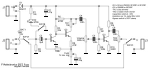
Here’s my evolved Fuzz Face. Standard fuzz circuit with a bias trimmer and everything exactly as before. Minus the reverse logarithmic taper for the fuzz pot. The output has been dramatically improved.
There is nothing exactly new or special about it. If we look at some details, there are your modern standard 3PDT stomp for true bypass, including a 1M pulldown resistor at the input to address possible pop side effects caused by mechanical switching. One could, of course, use way higher value for that resistor to prevent it from loading the input. This switching method also grounds the circuit input when bypassed and there’s a 12k resistor for bright white LED too. DC connection is wired for standard battery (which i never use for my builds) switching, which takes the battery connection out once the input jack has been disconnected. Power supply section has a 47µ filter cap and a series polarity protection (taken care of by low voltage drop Schottky). The base topology for the fuzz is in tact with its 2µ2 input cap, bias trimmer and a swapped reverse logarithmic fuzz control pot. There are other ways to gain reasonable sweep for this control by creating a custom taper, but for this drawing we’ll settle for rev. log. Some might have noticed that the fuzz output cap value in both of my drawing is 100n. Many similar designs have a lot lower value in that position, which leads to more tighter, trebly and nasal overall tone, especially when the level control is maxed. Personally i like the feel of a fatter tone, so 47n or 100n for me. Now all up to this point will produce the same tone as the smaller, more generic example.
The rest of the circuit is not completely different from one classic one transistor booster marketed by one Electro-Harmonix. It is a simple one transistor amplifier with low parts count that colors tone tone only a little. The output of this amplifier is coming to a 100k trimpot which acts as a Master Level trim.
Why do you have the level control for the fuzz where it originally was? Why not use that Master Level as an level control?
Good question. And i have a simple answer. To keep the frequency responce of the fuzz as close to the original as possible. Since the boost amplifier colors the tone only a little, we don’t want its output to change the frequency response in the same manner as the fuzz’s level control does. Instead of this arrangement, we coud use a JFET or even an opamp to boost the ouptut, but former would be better off with a bias trimmer and the latter would need its own refence voltage network. To keep everything simple and neat, its not a bad practice to go with this solution. Ah. There would be so much more to talk about what’s going on with this circuit. But i’m going to leave you with the information above and two notes – Breadboard it. Fuzz face is a highly tweakable and good sounding tiny circuit. There is always room for more and more tweaking. You should try to make it better for yourself. And another; want one? Sure, i can build you one..


Leave a Reply